Service Kit : If complete would be $8,414.00
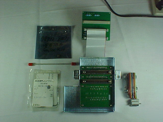
The service kit (08712-60012) for the 871x series analyzers contains several parts that are useful for adjusting and servicing the analyzer. The following parts are included:
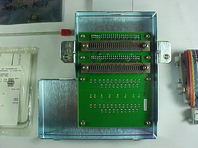
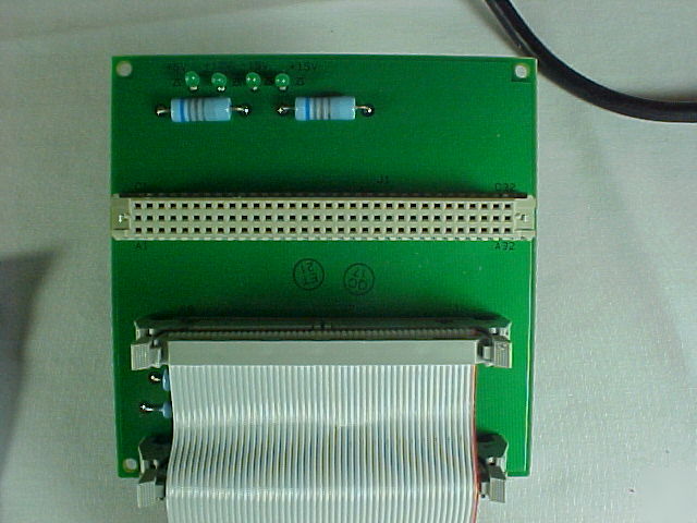
• extender board assembly that allows you to operate selected internal board assemblies outside the analyzer chassis
• GPIB connector extender that allows you to mate an GPIB cable when the extender board assembly is attached to the analyzer
• two SMB extension cables, 12 inches long (30-cm)
• modified 5/16-inch wrench for better access to SMA cable nuts
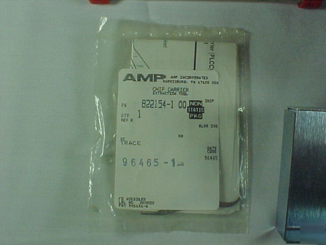
• IC extractor tool for removing ICs such as the U335 bootROM
• 6-inch (150-mm) semirigid coaxial extension cable
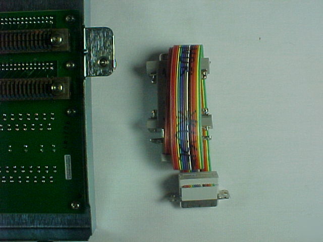
• non-shielded display ribbon cable used to connect the display when the A2 CPU board is operated outside the chassis
• voltage reference source used to perform several adjustments. The source provides ±0.5 V, ±24 mV, and +10 V supplies.
• two "minimum configuration" bootROMs (one is for model 871xC)
• spare limiter to facilitate troubleshooting
The CPU (A2), fractional-N/reference (A3), source (A4), and receiver (A5) board assemblies can all be operated outside of the chassis with the extender board. This can be very helpful if you are troubleshooting a problematic board or assembly.
The supplied display ribbon cable is needed to connect to the display if the CPU assembly is connected to the extender board.
The SMB extension cables may be needed for the fractional-N/reference or source assemblies.
The A4 source and A5 receiver assemblies will need two flexible SMA RF cables (not supplied) to make the analyzer fully operational while either of these boards are connected to the extender board.
To use the extender board, follow these instructions:
1. Loosen the two screws on the back cover of the analyzer.
2. Slide the cover to the right and remove it.
3. Attach the lower half of the extender assembly to where the cover was previously located.
4. Align the hold-down screws and tighten securely; the board will not function if not tightened sufficiently.
5. Attach the two ribbon cable connectors as shown in
The board under test plugs into the 96-pin connector. When properly connected, both the top half of the extender assembly and the attached board under test can rest on top of the analyzer.
If it is necessary to connect a computer to the analyzer while using the extender board, then the GPIB connector extender (supplied) will be required in order to make a connection.
If you have any questions please ask.
California sales are taxable at 7.75% unless resale number is on file and verified.