Adaptor PCB converts surface mount IC footprints to 0.100" pin spacing.
Boards contains 54 tiled individual chip carriers uncut - you must cut and separate them yourself.
( Originally manufactured for a reseller who was cutting and reselling the individual tiles for $1 to $2 per carrier! Cut apart yourself and save! )
Board is already v-scored in one direction, remains to be cut in the other direction. V-scores penetrate 90% of the PCB thickness. Can be separated with little effort.
27 for SOIC 8 pin ( .05" pitch)
18 for TSOP / MSOP 8 pin (0.025" or 0.65mm pitch)
4 for TSOP / MSOP 20 pin (0.025" or 0.65mm pitch)
2 for SOIC 8 converted to Single-in-line
Takes standard 0.100 header pins for legs. Header pins not included
High quality FR4 double-sided, plated-thru and tinned holes, with conformal coating and solder mask.
Most tiles also provide thermal lands to accomodate IC's with exposed metal thermal pads. These lands are "stitched" to the opposite side of the PCB with thermal vias to conduct heat away from the chip. These surfaces can also be used as ground planes in chips that don't have an exposed thermal pad.
Individual tiles can be cut with a Dremel tool and a router table accessory (using a thin cutoff wheel).
This can also be done by repeated scoring with a sharp utility blade (score a "V" groove rathen than scoring perpendicular). For best results, do not cut the PCB all the way through - score only deep enough to allow separation by hand later.
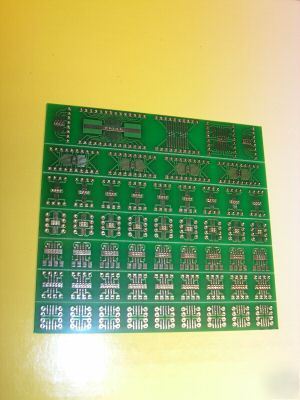
Below: TOP side of PCB, showing v-scores
Pattern Description: From the bottom
Row 1 is the most compact configuration for SOIC8. Just 0.4" between rows, and easiest to solder, but resulting pinout is not 1-2-3-4. (it is what's called a compact pinout) Need to keep this in mind when connecting /breadboarding
Row 2 patterns take up more space than row 1, 0.5" accross, but yields a 1-2-3-4 pinout.
Row 3 brings all pins to the same edge, 1-2-3-4 pinout, with 5-6-7-8 on the reverse side. Uses a 4x2 header strip to save the most board space by standing the carrier vertically.
Rows 4 and 5 are just like rows 1 and 2 , but for 0.025 pitch IC's.
Row 6 takes higher pin counts in 0.025 pitch. It can carry any pin count from 10 through 20 pins, and accomodate IC widths as narrow as 0.12" and as wide as 0.44". It's made to be as universal as possible, and to maintain small size, it has compact pinout.
Row 7 provides higher pin counts for SOIC IC's: one with 1-2-3-4 pinout, the other with a compact pinout.
Also on row 7, a 0.025 pitch carrier for IC's with 10 through 28 pins.
Also on row 7, 2 SOIC-8 carriers with single-in-line pinouts, suitable for breadboarding. (row 3 cannot breadboard, due to 0.100 spacing between rows.)
US: $3.75 Canada: $4.50 International: $5.50 Economy option.
2-nd item: saves 50% of its S&H
items 3, 4: each saves 60% off their S&H
items 5, 6, 7: each saves 70% off their S&H
items 8 and higher: save 80% off their S&H
Items are ordered highest S&H amount first.
Be sure to add me to your favorites list!